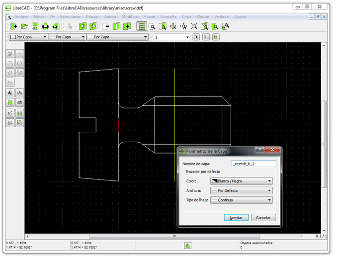

One successful workaround is to generate the image in PDF format, import it into imaging software ( GIMP, as an example again, has the capability and is free & open source), and modify/save as needed. As noted previously, the image exporting capability of LibreCAD alone does not seem to be working as intended for that task. Knowing that the pen widths will show as intended is also likely to be necessary in such a case. For example, an academic journal may require an image of a schematic to be at least 4" in any one direction, 300 DPI or greater, and TIF format. Step 2 With your crosshair cursors, click where you want to place the lower-left corner of your image. In the dialog window that pops up, locate your image file and open it up. Generate an Image File with Specific PropertiesĬertain circumstances require the generation of an image file with specific properties. Here’s the basic process of opening up your standard raster image on LibreCAD: Opening a raster image in LibreCAD Step 1 Click on File > Import > Insert Image. The intent is not to mirror related Issues in the GitHub repository, but to present workarounds to accomplish specific tasks. (Note that there appear to be issues with both functionality and clarity of the image export options.) Choose location, file name, and file type.There appear to be issues defining dimensions and resolution. The image exporting capability does not seem to be working as intended. "Image" covers a number of raster and vector formats, including SVG. Confirm through File->Print Preview that desired scale, positioning, and black & white/color options have been selected.An illustration of a persons head and chest. Clicking the mouse should result in a line angled up and to the left. With the Snap on Endpoints enabled, click close to the end of the line at absolute coordinate 135,60.
LIBRECAD PDF IMPORT MANUAL

Note that the options selected in Print Preview define aspects of the PDF output. 4.1 Generate an Image File with Specific Properties.


 0 kommentar(er)
